
TL;DR

Get garage and car supplies delivered free — and shop member deals
- Fast, free delivery on millions of items
- Access to Prime Big Deal Days deals on October 6–7
- Prime Video, Amazon Music and more included
A Charged EVs report outlines how PXI-based switching and sensor simulation can automate hardware-in-the-loop tests of vehicle electronic control units. It describes simulated electrical faults and sensor inputs for applications including braking and EV battery management, while specific performance comparisons and independent validation are not provided.
A technical report published by Charged EVs describes using PXI-based switching to inject electrical faults and simulate sensor signals during tests of vehicle electronic control units (ECUs). The approach is intended to let engineers test how controllers respond to normal and faulty inputs without creating those conditions on a physical vehicle or repeatedly rewiring a manual patch panel.
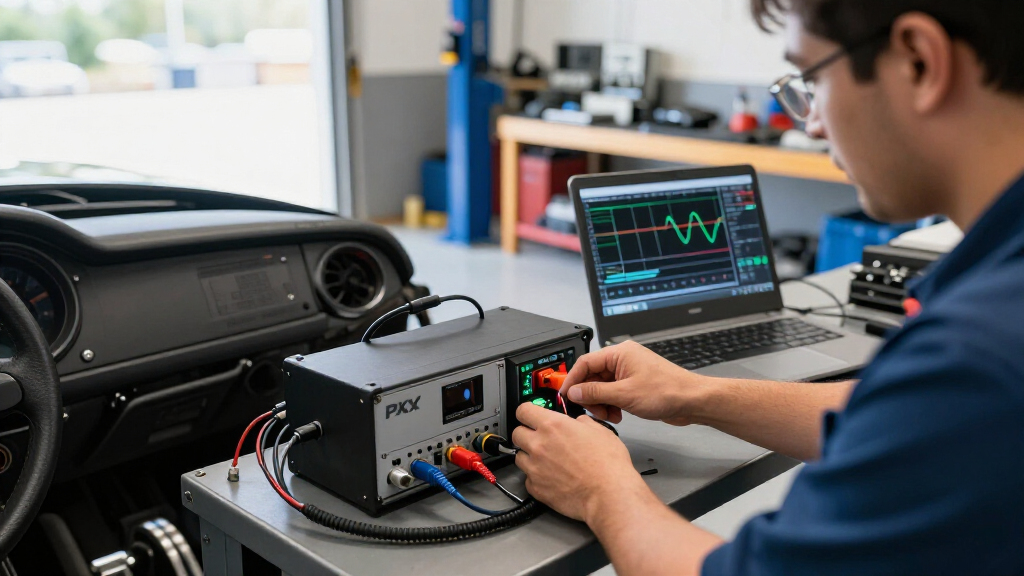
In hardware-in-the-loop simulation, a test platform supplies signals that stand in for real sensors, while instruments measure the ECU’s outputs. The report says this setup can be used from early design work through production testing. It gives an anti-lock braking system as an example: engineers can simulate a failed wheel-speed sensor while checking the controller’s response to braking inputs.
The described PXI arrangement places switching modules between the simulator and the device under test. Software can route signals normally or apply selected faults, including open circuits, shorts between pins, shorts to ground or power, and resistive faults. The report presents this as a way to make test sequences repeatable and reduce manual intervention compared with moving cables on a patch panel.
The report also describes modules for simulating several sensor types used in vehicle systems: thermocouples, LVDTs, RVDTs and resolvers, and 4–20 mA current loops. For battery management system tests, it identifies cell simulator modules with two, four or six isolated cells per module, specified accuracy of ±5 mV from 1 V to 7 V, and a 750 V isolation barrier. These specifications are reported by the source; no independent test results are included in the supplied material.
Repeatable Tests for Vehicle ECUs
ECUs control functions that can affect vehicle safety and, in electric vehicles, battery operation. Testing how a controller behaves when sensor signals fail can help identify faults before a system is installed in a vehicle. HILS provides a way to exercise those responses using simulated inputs, according to the report.
The report’s case for PXI centers on automation and reuse. Software-controlled routing may make it easier to run the same fault sequence again and to record results, while a modular platform can be adapted across test programs. The source says this could reduce duplicated engineering work and support use from prototype validation through production. It does not provide measured cost savings, throughput figures or a direct comparison with other test platforms, so the scale of those benefits remains unquantified.
PXI switching modules for automotive testing
As an affiliate, we earn on qualifying purchases.
As an affiliate, we earn on qualifying purchases.
From Patch Panels to PXI
Traditional fault insertion often uses a manual patch panel connecting ECU input and output lines to stimulus and measurement equipment. As described in the report, an engineer can disconnect a line to create an open circuit or connect lines to simulate a short, then measure the response. Repeating the process requires further cable changes.
The source identifies bench space, test speed, repeatability and labor as limitations of manual patching, particularly where many fault cases must be run. It describes PXI as a modular standard with chassis-level timing and triggering, and says switching modules can be placed in a PXI chassis or, when switching noise is a concern, a separate LXI/USB chassis. It names Pickering Interfaces as a supplier of fault-insertion units and Bloomy as an integrator whose Universal Test System combines switching and simulation. Those vendor examples come from the report.
sensor simulation hardware for vehicle ECUs
As an affiliate, we earn on qualifying purchases.
As an affiliate, we earn on qualifying purchases.
Performance Data Not Supplied
The supplied report material does not identify a publication date, a specific ECU test program, or results from a comparative evaluation. It also does not quantify how much faster or less costly PXI-based testing is than manual patching, or specify how many fault combinations a particular setup can run.
Although the source lists module capabilities and electrical ranges, it does not provide independent verification of those specifications or explain how the described configuration maps to a particular vehicle certification requirement. The effect of fault insertion on a given ECU’s safety case will depend on the test design and applicable requirements.
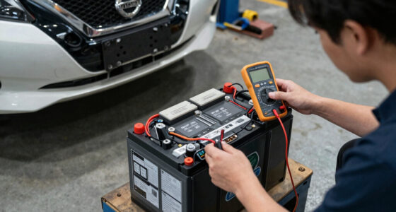
fault injection test equipment for electric vehicles
As an affiliate, we earn on qualifying purchases.
As an affiliate, we earn on qualifying purchases.
Application Depends on Test Design
The next step for teams considering this method is to define the ECU signals, fault cases and sensor types their test program must cover, then select and configure suitable switching and simulation modules. Engineers would also need to verify that the setup reproduces the required electrical conditions and records results in a form suitable for their development or production process.
The report does not announce a new product launch, a customer deployment or a scheduled milestone. Further details about specific configurations, measured benefits and validation results would be needed to assess how the approach performs in a particular test environment.
As an affiliate, we earn on qualifying purchases.
Key Questions
What does PXI-based fault insertion do?
It uses software-controlled switching to pass signals to an ECU or apply selected electrical faults, such as an open circuit or short, during a test.
What is hardware-in-the-loop simulation?
HILS connects a real controller to a test platform that simulates the signals and operating environment it would encounter in a vehicle. Instruments measure the controller’s outputs.
Which sensor types does the report cover?
The report describes simulation for thermocouples, LVDTs, RVDTs, resolvers and 4–20 mA current loops, as well as cell simulation for battery management system tests.
Does the report quantify cost or speed improvements?
No. It describes potential advantages such as repeatability and reuse, but the supplied material gives no measured cost savings or test-speed comparison.
Source: rss
Halloween Picks
halloween
As an affiliate, we earn on qualifying purchases.